Getting Started
caution
This doc might be out-dated. Please see the examples for the most up-to-date syntax.
Tutorial Outline#
The programming with BHDL consists of several steps:
- Component Selection. The information needed are:
- the Pin definition of the IC
- specify the desired footprint
- Use
make-circuitAPI to compose your circuit. Optionally, hierarchical compose your more complex circuit usingmake-circuit. Eachmake-circuitAPI expects several components:- what the external pins are
- connect the components using the 4 types of connection syntax
- specify physical layout of components
- Expose your design via
circuit-exportAPI, to KiCAD, PDF, BOM, etc.
In this guide, we will go over these steps using a simple keyboard example. We will assume you have a jupyter notebook opened with IRacket kernel. Please refer to the setup documents if you need to setup one, or use our online server.
Setting up#
The first step is to use the BHDL library via:
Note that you must setup BHDL_LIBRARY_PATH ENV variable to your footprint path before requiring the BHDL library.
We probably also need some racket libraries:
We'll want to add some global signals to refer:
The keyboard matrix#
The components:
- Kailh hot-swap socket:
kailh-socket - Diodes:
1N4148W
We can call the key-with-diode to create this small circuits for each key.
The matrix variable holds 4x5 keys. We then connect them together:
We note several points here:
- We don't use `
#:varsto create components, because we are using thematrixvariable that is already created - We specify 4+5 external pins for rows and columns, respectively
- We use a loop to connect the external row and column pins to the corresponding key in the matrix.
- Finally, we specify the layout to be *horizontally append" (via
hc-appendAPI) to form the rows and "vertically append" (viavc-appendAPI) to form the columns.
The end result of the key matrix module looks like this:
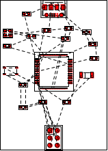
The MCU board#
The components:
- Atmega32U4
- Micro USB connector
- 16MHz Crystal
- Resistors, Capacitors, LEDs will be created "inline"
The variables, external pins and layout looks like this:
Some notes about this code snippets:
#:varssection: We create several "big components" in the#:varsdeclaration, including the MCU, USB connector, ICSP header and crystal, because they have multiple pins and we want a handle variable to refer to them. All other components like resistors and capacitors are created "inline", where we don't really want to give them a name.#:external-pinssection: The external pin of this module is 4+5 pins for row and column scanning of the key matrix.#:layoutsection: We layout the USB, MCU and ICSP header to be vertically appended. We don't care much about the locations of other components such as the resistors, capacitors. They will be placed by our automatic placement engine to appropriate locations by optimizing the total wire length (formally HPWL).
There are a lot of staff going on in the connection section, and we'll describe them in small sections. First, the ICSP connector for flashing firmware:
Then the Power module including reset and switch:
The crystal module:
The USB connector:
Finally, we select some GPIO pins for row and column scanning the matrix:
The end result would looks like this:
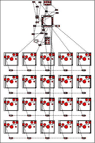
Connecting the MCU module and Matrix Module#
This is simply:
And we export the keyboard to KiCAD, PNG, BOM:
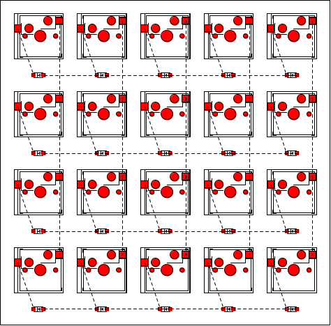
The keyboard looks like this:
The BOM.csv contains the mapping from the annotations (e.g. U1, R4, D3) to the component name, footprint, and value.
| Annotation | Name | Footprint | Values |
|---|---|---|---|
| U36 | kailh-socket | 1 | () |
| D37 | 1N4148W | #f | () |
| U38 | kailh-socket | 1 | () |
| D39 | 1N4148W | #f | () |
| U40 | kailh-socket | 1 | () |
| U41 | ATmega16U4/ATmega32U4 | TQFP-44 | () |
| U42 | USB-Micro | #f | () |
| U43 | PinHeader2 | 3 | () |
| U44 | Crystal-4 | #f | (16MHz) |
| R45 | Resistor/R | 0603 | (1k) |
| LED46 | LED0603 | #f | (red) |
| D47 | LL4148 | #f | () |
| R48 | Resistor/R | 0603 | (10k) |
| KEY49 | SKRPACE010 | #f | () |
| C50 | Capacitor/C | #f | (1uf) |
| C51 | Capacitor/C | #f | (1uf) |
| C52 | Capacitor/C | #f | (100nf) |
| C53 | Capacitor/C | #f | (100nf) |
| C54 | Capacitor/C | #f | (100nf) |
| C55 | Capacitor/C | #f | (100nf) |
| C56 | Capacitor/C | #f | (22pf) |
| C57 | Capacitor/C | #f | (22pf) |
| R58 | Resistor/R | 0603 | (22) |
| R59 | Resistor/R | 0603 | (22) |
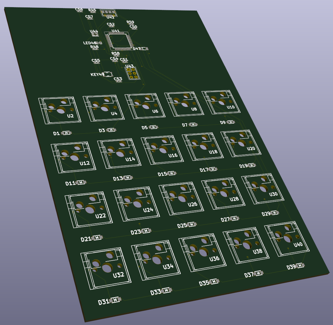
The .kicad_pcb file can be opened by the popular open source PCB EDA software KiCAD. The routing can be done by the open source freerouting software automatically. The end board is manufacture-ready, and looks like this in KiCAD's 3D-viewer: